MICROCONTROLLER PROGRAMMING AND ACCESS CONTROL SYSTEMS 3

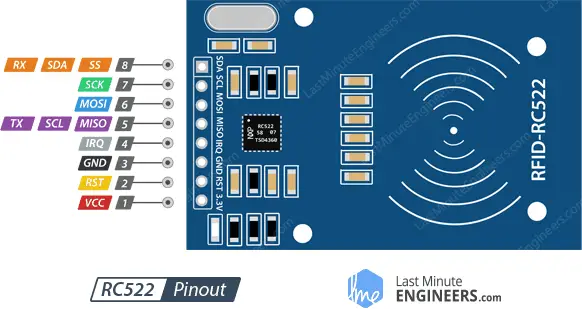
Here, we'll learn and understand first how an RFID(Radio Frequency Identification)Module works then proceed to use this knowlege to control the opening and closing of a relay.
An RFID system consists of 2 main parts, a tag and a
reader
A tag is placed on the object to be identified while a reader is on the module.The reader consists of a radio frequency module and an antenna that generates a high frequency electromagnetic field while the
reader is a passive device(doesn't require power) which consists of a microchip that stores and processes information and an antenna for receiving and transmitting a signal.
When the tag is brought close to the reader, the reader generates
an electromagnetic field. This causes electrons to move through the tag's antenna and subsequently powers the chip.
The chip then responds by sending its stored information back to the reader in the form of another radio signal.
This is called a backscatter. The reader detects and interprets this backscatter and sends the data to a computer or microcontroller.
The above content describes the principle of operation of an RFID module when used as an Access
control System.
This module can also be used in other applications such as:
    from machine import Pin
    import ssd1306
    from mfrc522 import MFRC522
    from time import sleep
    '''
    RSP Pico  |   RC522
    0         |   RST
    1         |   SDA
    2         |   SCK
    3         |   MOSI
    4         |   MISO
    '''
    #Initializing the relay.
    relay=Pin(5,Pin.OUT)

    #Initializing the RFID card reader.
    reader = MFRC522(spi_id=0,sck=2,miso=4,mosi=3,cs=1,rst=0)

    #List of card IDs that are granted access.
    cards=["1497272400"]

    print("Bring TAG closer...")
    print("")

    while True:
        reader.init()
        (stat, tag_type) = reader.request(reader.REQIDL)
        if stat == reader.OK:
            (stat, uid) = reader.SelectTagSN()
            if stat == reader.OK:
                card = int.from_bytes(bytes(uid),"little",False)
                print("CARD ID: "+str(card))
                if str(card) in cards:
                    print("Access granted")
                    relay.value(1)
                    sleep(1)
                    relay.value(0)
                else:
                    print("Access denied")
        sleep(0.5)
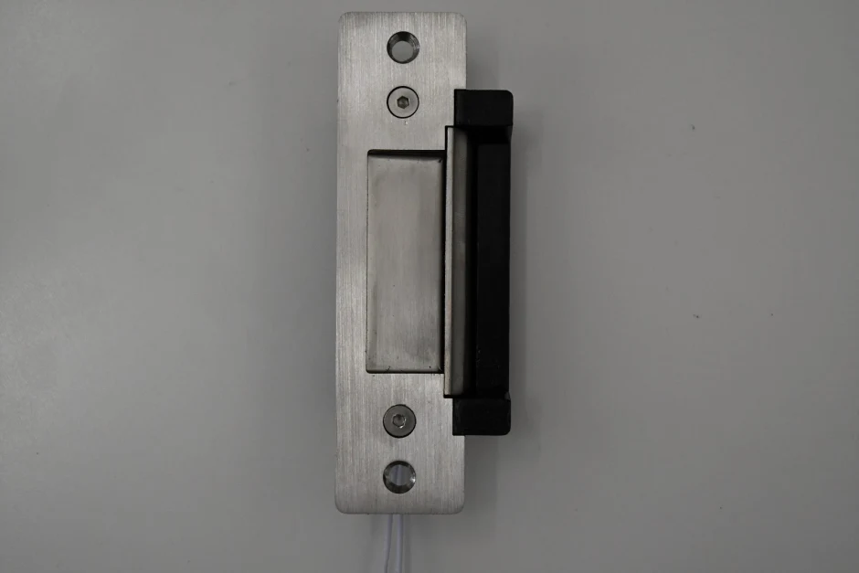
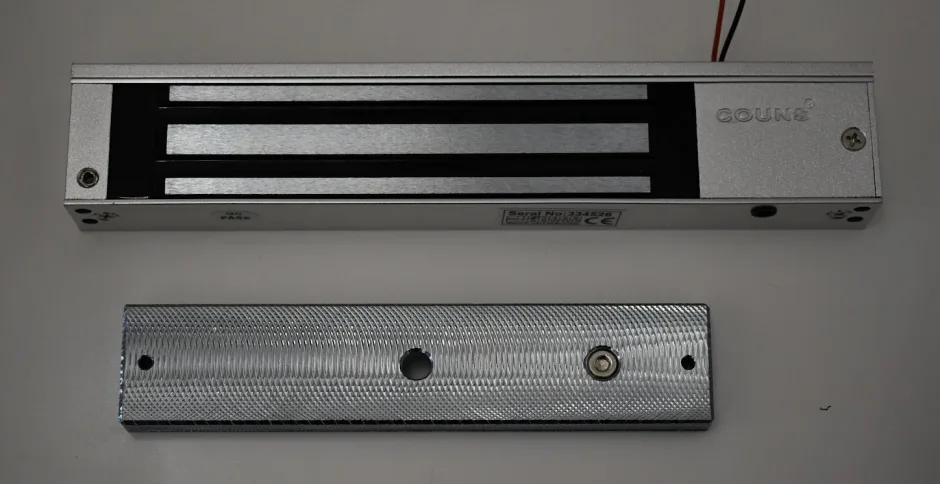
Door locks have been in use for a large chunck of human civilization history as they offered simple ways to secure rooms with valuables inside. They were simple at first such as the Egyptian Tumbler Lock but gradually became more complex to
the modern locks that use physical keys. As technology continued to advance, locks were invented that did not require physical keys to open. It began by using a physical code such as combinational locks then more recently we adopted the
use of wireless codes(keys) sent via radio frequencies that can be read by an RFID reader used in the RFID access control.
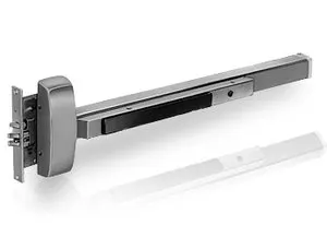
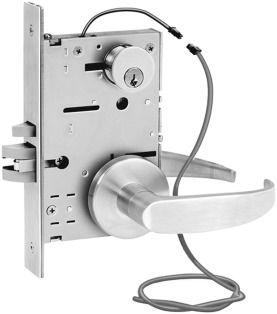
Wireless keys are mostly used in Electric locks which are opened or closed by use of electrical energy.They
come two configurations:
from machine import SoftSPI,ADC,Pin
import ssd1306
from mfrc522 import MFRC522
from time import sleep

#Initializing the card reader
reader = MFRC522(spi_id=0,sck=2,miso=4,mosi=3,cs=1,rst=0)
cards=["1497272400"]

print("Bring TAG closer...")
print("")

#initializing the OLED Display
spi=SoftSPI(baudrate=50000,polarity=1,sck=Pin(14),mosi=Pin(13),miso=Pin(12))
dc = Pin(6)   # data/command
rst = Pin(5)  # reset
cs = Pin(15)  # chip select, some modules do not have a pin for this

display = ssd1306.SSD1306_SPI(128, 64, spi, dc, rst, cs)

#initializing the relay and green led
relay=Pin(11,Pin.OUT)
greenLed=Pin(10,Pin.OUT)

#initializing the buzzer
buzzer=Pin(9,Pin.OUT)

x=50
y=0
z=1
diff=5

while True:
    display.fill(0)
    reader.init()
    (stat, tag_type) = reader.request(reader.REQIDL)
    if stat == reader.OK:
        (stat, uid) = reader.SelectTagSN()
        if stat == reader.OK:
            card = int.from_bytes(bytes(uid),"little",False)
            display.text('CARD ID: '+str(card),0,0,1)
            if str(card) in cards:
                print("Access granted")
                display.text("Access granted!",0,10,1)
                display.show()
                relay.value(1)
                greenLed.value(1)
                sleep(2)
                relay.value(0)
                greenLed.value(0)
                display.fill(0)
            else:
                print("Access denied")
                display.text("Access DENIED!",0,10,1)
                greenLed.value(1)
                display.show()
                buzzer.value(1)
                sleep(3)
                buzzer.value(0)
                display.fill(0)
    else:
        display.text("BRING",x,y,z)
        display.text("CARD",x+2,y+10,z)
        display.text("CLOSER",x-4,y+20,z)
        y=y+diff
        if y>=35 or y<=0:
            diff=diff*-1
        display.show()
    sleep(1)
The following is the video of the RFID Access control System prototype.