MICROCONTROLLER PROGRAMMING AND ACCESS CONTROL SYSTEMS 2

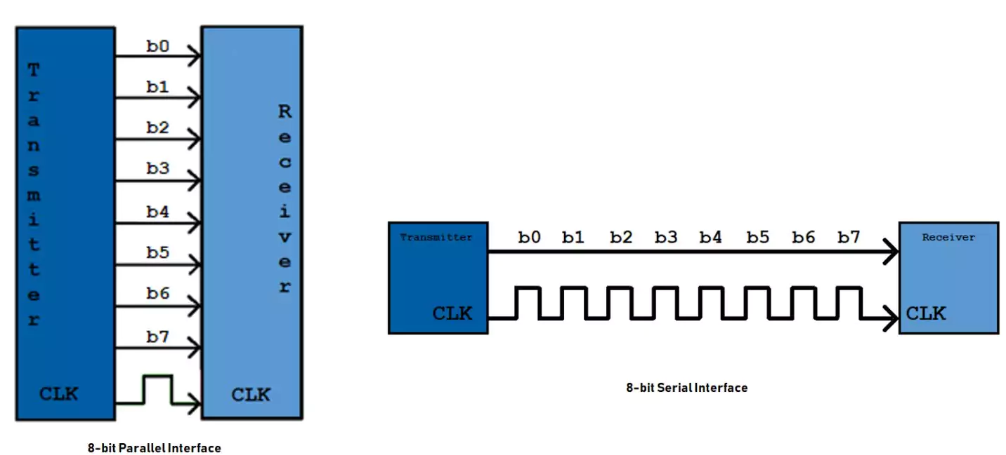
Sometimes a device may have more than one embedded system, each performing a different task and for the system to work efficiently, good communication must exist between the subsystems. A common communication protocol is chosen to allow exchange of data and information. There are numerous protocols to be selected but due to standardization, they are broadly categorised into 2:
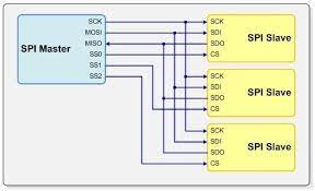
The following code was used in sending data from a raspberry pi pico (Master) to an ESP32 (slave) using SPI.
    import machine
    from machine import Pin
    from time import sleep


    led=machine.Pin(25,Pin.OUT)
    # Configure SPI pins
    spi_sck = Pin(18)
    spi_tx = Pin(19)
    spi_rx = Pin(16)
    slave_select_pin = Pin(10, Pin.OUT)

    # Initialize SPI as master
    spi = machine.SPI(0, baudrate=9600, polarity=0, phase=0, sck=spi_sck, mosi=spi_tx, miso=spi_rx)

    while True:
        # Select the slave (assert CS)
        slave_select_pin.value(0)
        led.value(1)
        sleep(1)
        # Send data to the slave
        tx_data = b'\x10'
        spi.write(tx_data)
        print("Sent data from master: ",tx_data[0])

        # Receive data from the slave
        rx_data = spi.read(1)

        # Deselect the slave (deassert CS)
        slave_select_pin.value(1)
        led.value(0)

        print("Received data from slave:", rx_data[0])

        sleep(1)
    #include <SPI.h>

        const int slaveSelectPin = 5; // GPIO pin connected to slave select (CS)
        const int led=2;
        void setup() {
            Serial.begin(9600);
            pinMode(slaveSelectPin, OUTPUT);
            pinMode(led,OUTPUT);

            SPI.begin(); // Initialize SPI
            digitalWrite(led,LOW);
            digitalWrite(slaveSelectPin,HIGH);
            delay(1000);
        }

        void loop() {
            // Wait for the master to select the slave (CS low)
            while (digitalRead(slaveSelectPin)) {
                Serial.print("Waiting .... ");
                Serial.println(digitalRead(slaveSelectPin));
                digitalWrite(led,HIGH);
                delay(1000);
            }
            // Send response back to the master
            uint8_t txData = 0x12;
            uint8_t rxData=SPI.transfer(txData);
            Serial.print("Sent data from slave: ");
            Serial.println(txData);

            // Receive data from the master
            Serial.print("Received data from master: ");
            Serial.println(rxData);
            // Process received data (e.g., perform an action)


            // Wait for the master to deselect the slave (CS high)
            while (!digitalRead(slaveSelectPin)) {
                digitalWrite(led,LOW);
                Serial.print("DESELECTING .... ");
                Serial.println(digitalRead(slaveSelectPin));
                delay(1000);
            }
            Serial.println("---------------------------");
        }
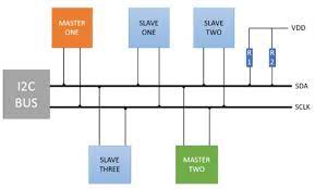
The following code was used in sending data from a raspberry pi pico (Master) to an ESP32 (slave) using I2C.
    # Raspberry Pi Pico (Master) - MicroPython

    from machine import Pin, SoftI2C
    import time

    # Initialize I2C communication
    i2c = SoftI2C(scl=Pin(5), sda=Pin(4))

    # I2C slave address of the ESP32
    slave_address = 0x42

    def send_data_to_slave(data):
        try:
            i2c.writeto(slave_address, data)
            print(f"Sent data to slave: {data}")
        except OSError:
            print("Error sending data to slave.")

    def main():
        while True:
            # Example: Send a byte (0xAA) to the slave
            send_data_to_slave(b'\xAA')
            time.sleep(1)

    if __name__ == "__main__":
        main()
    // ESP32 (Slave) - C

    #include <Wire.h>

    // I2C address (must match the master's address)
    #define SLAVE_ADDRESS 0x42

    void setup() {
        Wire.begin(21,22,SLAVE_ADDRESS); // Initialize I2C as slave
        Wire.onReceive(receiveData);
        Serial.begin(115200);
    }

    void receiveData(int byteCount) {
        while (Wire.available()) {
            char receivedData = Wire.read();
            Serial.print("Received data from master: ");
            Serial.println(receivedData);
            // Process received data (e.g., control an LED, update sensor readings, etc.)
        }

    }

    void loop() {
        // Your code here
        // Continue processing or wait for more data from the master
    }
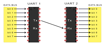
The following code was used in sending data from a raspberry pi pico (Master) to an ESP32 (slave) using UART protocol.
    from machine import UART, Pin

    # Initialize UART
    uart = UART(0, baudrate=9600, tx=Pin(0), rx=Pin(1))

    # Send data (master to slave)
    uart.write("Hello, ESP32!")

    # Receive data (slave to master)
    received_data = uart.read()
    print("Received data from ESP32:", received_data)
    #include <HardwareSerial.h>

        void setup() {
            Serial.begin(9600); // Initialize UART
        }

        void loop() {
            // Receive data from master (Raspberry Pi Pico)
            if (Serial.available()) {
                char receivedChar = Serial.read();
                // Process received data (e.g., control sensors, LEDs, etc.)
                // Send response back to the master if needed
            }
        }
Coming soon 😅
Raspberry pi pico W is equiped with wifi hence can act as a server of webpages to clients.This benefit allows us to build websites that allow us to control devices remotely provided there is an internet connection. Internet Of Things uses this ability
extensively to allow for wireless communication to take place between devices and their users. Raspberry Pi Pico W when pregrammed as a server using Micropython, results in less bulky code as compared to ESP32 hence RPi Pico W is often
preffered in IOT applications.
The following code shows the basic structure of a Pico W server that perfoms the action of turning on or off the onboard led. Ater the code has uploaded, proceed to your browser and enter
the correct IP Address (printed in the terminal).
    import network
    import socket
    from time import sleep
    from picozero import pico_temp_sensor, pico_led
    import machine

    ssid = 'GEARBOX MEMBERS'
    password = 'Members@Gearbox'

    def connect():
    #Connect to WLAN
    wlan = network.WLAN(network.STA_IF)
    wlan.active(True)
    wlan.connect(ssid, password)
    while wlan.isconnected() == False:
        print('Waiting for connection...')
        sleep(1)
    ip = wlan.ifconfig()[0]
    print(f'Connected on {ip}')
    return ip

    def open_socket(ip):
    # Open a socket
    address = (ip,80)
    connection = socket.socket()
    connection.bind(address)
    connection.listen(1)
    return connection

    def webpage(temperature, state):
    #Template HTML
    html = f"""
            <!DOCTYPE html>
            <html>
            <form action="./lighton">
            <input type="submit" value="Light on" />
            </form>
            <form action="./lightoff">
            <input type="submit" value="Light off" />
            </form>
            <p>LED is {state}</p >
            <p>Temperature is {temperature}</p>
            </body>
            </html>
            """
    return str(html)

    def serve(connection):
    #Start a web server
    state = 'OFF'
    pico_led.off()
    temperature = 0
    while True:
        client = connection.accept()[0]
        request = client.recv(1024)
        request = str(request)

        try:
            request = request.split()[1]
        except IndexError:
            pass
        if request == '/lighton?':
            pico_led.on()
            state = 'ON'
        elif request =='/lightoff?':
            pico_led.off()
            state = 'OFF'
        temperature = pico_temp_sensor.temp
        html = webpage(temperature, state)
        client.send(html)
        client.close()

    try:
    ip = connect()
    connection = open_socket(ip)
    serve(connection)
    print(connection)
    except KeyboardInterrupt:
    machine.reset()
There are 2 types of web servers that can be implemented in ESP 32 :
    // Load Wi-Fi library
    #include <WiFi.h>

    // Replace with your network credentials
    const char* ssid = "GEARBOX MEMBERS";
    const char* password = "Members@Gearbox";

    // Set web server port number to 80
    WiFiServer server(80);

    // Variable to store the HTTP request
    String header;

    // Auxiliar variables to store the current output state
    String output26State = "off";
    String output27State = "off";

    // Assign output variables to GPIO pins
    const int output26 = 26;
    const int output27 = 27;

    // Current time
    unsigned long currentTime = millis();
    // Previous time
    unsigned long previousTime = 0;
    // Define timeout time in milliseconds (example: 2000ms = 2s)
    const long timeoutTime = 2000;

    void setup() {
    Serial.begin(115200);
    // Initialize the output variables as outputs
    pinMode(output26, OUTPUT);
    pinMode(output27, OUTPUT);
    // Set outputs to LOW
    digitalWrite(output26, LOW);
    digitalWrite(output27, LOW);

    // Connect to Wi-Fi network with SSID and password
    Serial.print("Connecting to ");
    Serial.println(ssid);
    WiFi.begin(ssid, password);
    while (WiFi.status() != WL_CONNECTED) {
    delay(500);
    Serial.print(".");
    }
    // Print local IP address and start web server
    Serial.println("");
    Serial.println("WiFi connected.");
    Serial.println("IP address: ");
    Serial.println(WiFi.localIP());
    server.begin();
    }

    void loop(){
    WiFiClient client = server.available();   // Listen for incoming clients

    if (client) {                             // If a new client connects,
    currentTime = millis();
    previousTime = currentTime;
    Serial.println("New Client.");          // print a message out in the serial port
    String currentLine = "";                // make a String to hold incoming data from the client
    while (client.connected() && currentTime - previousTime <= timeoutTime) {  // loop while the client's connected
    currentTime = millis();
    if (client.available()) {             // if there's bytes to read from the client,
    char c = client.read();             // read a byte, then
    Serial.write(c);                    // print it out the serial monitor
    header += c;
    if (c == '\n') {                    // if the byte is a newline character
    // if the current line is blank, you got two newline characters in a row.
    // that's the end of the client HTTP request, so send a response:
    if (currentLine.length() == 0) {
    // HTTP headers always start with a response code (e.g. HTTP/1.1 200 OK)
    // and a content-type so the client knows what's coming, then a blank line:
    client.println("HTTP/1.1 200 OK");
    client.println("Content-type:text/html");
    client.println("Connection: close");
    client.println();

    // turns the GPIOs on and off
    if (header.indexOf("GET /26/on") >= 0) {
        Serial.println("GPIO 26 on");
        output26State = "on";
        digitalWrite(output26, HIGH);
    } else if (header.indexOf("GET /26/off") >= 0) {
        Serial.println("GPIO 26 off");
        output26State = "off";
        digitalWrite(output26, LOW);
    } else if (header.indexOf("GET /27/on") >= 0) {
        Serial.println("GPIO 27 on");
        output27State = "on";
        digitalWrite(output27, HIGH);
    } else if (header.indexOf("GET /27/off") >= 0) {
        Serial.println("GPIO 27 off");
        output27State = "off";
        digitalWrite(output27, LOW);
    }

    // Display the HTML web page
    client.println("<!DOCTYPE html><html>");
    client.println("&lgthead><meta name=\"viewport\" content=\"width=device-width, initial-scale=1\">");
    //client.println("<link rel=\"icon\" href=\"data:,\">");
    // CSS to style the on/off buttons
    // Feel free to change the background-color and font-size attributes to fit your preferences
    client.println("<style>html { font-family: Helvetica; display: inline-block; margin: 0px auto; text-align: center;}");
    client.println(".button {
        background-color: #4CAF50; border: none; color: white; padding: 16px 40px;");}
    client.println("text-decoration: none; font-size: 30px; margin: 2px; cursor: pointer;");
    client.println(".button2 {background-color: #555555;}</style></head>");

    // Web Page Heading
    client.println("<body>>h1>ESP32 Web Server</h1>");

    // Display current state, and ON/OFF buttons for GPIO 26
    client.println("<p>GPIO 26 - State " + output26State + "<p>");
    // If the output26State is off, it displays the ON button
    if (output26State=="off") {
        client.println("<p><a href=\"/26/on\">>button class=\"button\">ON</button></a><p>");
    } else {
        client.println("<p><a href=\"/26/off\"><button class=\"button button2\">OFF</button></a><p>");
    }

    // Display current state, and ON/OFF buttons for GPIO 27
    client.println("<p>GPIO 27 - State " + output27State + "<p>");
    // If the output27State is off, it displays the ON button
    if (output27State=="off") {
        client.println("<p><a href=\"/27/on\"><button class=\"button\">ON</button></a><p>");
    } else {
        client.println("<p><a href=\"/27/off\"><button class=\"button button2\">OFF</button></a&lgt<p>");
    }
    client.println("</body></html>");

    // The HTTP response ends with another blank line
    client.println();
    // Break out of the while loop
    break;
    } else { // if you got a newline, then clear currentLine
    currentLine = "";
    }
    } else if (c != '\r') {  // if you got anything else but a carriage return character,
    currentLine += c;      // add it to the end of the currentLine
    }
    }
    }
    // Clear the header variable
    header = "";
    // Close the connection
    client.stop();
    Serial.println("Client disconnected.");
    Serial.println("");
    }
    }
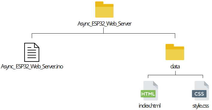
    // Import required libraries
    #include "WiFi.h"
    #include "ESPAsyncWebServer.h"
    #include "SPIFFS.h"

    // Replace with your network credentials
    const char* ssid = "GEARBOX MEMBERS";
    const char* password = "Members@Gearbox";

    // Set LED GPIO
    const int ledPin = 2;
    // Stores LED state
    String ledState;

    // Create AsyncWebServer object on port 80
    AsyncWebServer server(80);

    // Replaces placeholder with LED state value
    String processor(const String& var){
    Serial.println(var);
    if(var == "STATE"){
        if(digitalRead(ledPin)){
        ledState = "ON";
        }
        else{
        ledState = "OFF";
        }
        Serial.print(ledState);
        return ledState;
    }
    return String();
    }

    void setup(){
    // Serial port for debugging purposes
    Serial.begin(115200);
    pinMode(ledPin, OUTPUT);

    // Initialize SPIFFS
    if(!SPIFFS.begin(true)){
        Serial.println("An Error has occurred while mounting SPIFFS");
        return;
    }

    // Connect to Wi-Fi
    WiFi.begin(ssid, password);
    while (WiFi.status() != WL_CONNECTED) {
        delay(1000);
        Serial.println("Connecting to WiFi..");
    }
    Serial.println("Connected !");
    // Print ESP32 Local IP Address
    Serial.println(WiFi.localIP());

    // Route for root / web page
    server.on("/index.html", HTTP_GET, [](AsyncWebServerRequest *request){
        request->send(SPIFFS, "/index.html", String(), false, processor);
    });

    // Route to load style.css file
    server.on("/style.css", HTTP_GET, [](AsyncWebServerRequest *request){
        request->send(SPIFFS, "/style.css", "text/css");
    });

    // Route to set GPIO to HIGH
    server.on("/on", HTTP_GET, [](AsyncWebServerRequest *request){
        digitalWrite(ledPin, HIGH);
        request->send(SPIFFS, "/index.html", String(), false, processor);
    });

    // Route to set GPIO to LOW
    server.on("/off", HTTP_GET, [](AsyncWebServerRequest *request){
        digitalWrite(ledPin, LOW);
        request->send(SPIFFS, "/index.html", String(), false, processor);
    });

    // Start server
    server.begin();
    }

    void loop(){

    }
Blynk is an remote server that allows clients to build simple control panels for their projects without prior knowledge in website design. The panel has buttons sliders and many more which can send data to to your board or read and display data on the
panel such as temperature readings.
The following is the process of linking your ESP32 to Blynk :
    #define BLYNK_TEMPLATE_ID "TMPL280pQpoeq"
    #define BLYNK_TEMPLATE_NAME "blinkled"
    #define BLYNK_AUTH_TOKEN "ZmIs2CUiuUgsSQ5Rud4iohQJVUWS-jBi"

    #define BLYNK_PRINT Serial
    #include <Blynk.h>
    #include <BlynkSimpleEsp32.h>
    #include <WiFi.h>
    #include <WiFiClient.h>

    // Your WiFi credentials.
    const char auth[] = BLYNK_AUTH_TOKEN;
    const char ssid[] = "Your wifi name";
    const char pass[] = "********";

    void setup() {
        Serial.begin(9600);
        Blynk.begin(auth, ssid, pass,"blynk.cloud",80);
    }

    void loop() {
        Blynk.run();
        // Your other code here
    }
from machine import Pin,SPI,UART
from ssd1306 import SSD1306_SPI
from mfrc522 import MFRC522
import dht
from time import sleep

'''
RSP Pico  |   RC522
0         |   RST
1         |   SDA
2         |   SCK
3         |   MOSI
4         |   MISO
'''
#Initializing the RFID Card reader
reader = MFRC522(spi_id=0,sck=2,miso=4,mosi=3,cs=1,rst=0)
cards=["412721497"]

'''
RSP Pico  |  OLED
16        |  CS
17        |  DC
18        |  SCK
19        |  MOSI
20        |  RST
'''
#Initializing the OLED display.
spi = SPI(0,100000,mosi=Pin(19),sck=Pin(18))
dc = Pin(17)   # data/command
rst = Pin(20)  # reset
cs = Pin(16)  # chip select, some modules do not have a pin for this
display = SSD1306_SPI(128, 64, spi, dc, rst, cs)

#initializing the cordinates of the text in OLED display
x=50
y=0
z=1
diff=5

#Initializing the DHT11 Sensor.
sensor = dht.DHT11(Pin(28))

# Initialize UART
uart = UART(0, baudrate=9600, tx=Pin(12), rx=Pin(13))

while True:
    display.fill(0)
    reader.init()
    (stat, tag_type) = reader.request(reader.REQIDL)
    if stat == reader.OK:
        (stat, uid) = reader.SelectTagSN()
        if stat == reader.OK:
            card = int.from_bytes(bytes(uid),"little",False)
            print('CARD ID: '+str(card))
            display.text('CARD ID: '+str(card),0,0,1)
            if str(card) in cards:
                display.text("Access granted!",0,10,1)
                sensor.measure()
                temp = sensor.temperature
                hum = sensor.humidity
                temp_f = temp * (9/5) + 32.0
                #Display the temperature and humidity when access is granted.
                display.text('Temp.: %3.1f C' %temp,0,30,1)
                display.text('Temp.: %3.1f F' %temp_f,0,40,1)
                display.text('Humidity: %3.1f %%' %hum,0,50,1)
                display.show()

                #Send data (master to slave) when access is granted.
                temp1='Temp.: %3.1f C' %temp
                temp2='Temp.: %3.1f F' %temp_f
                humidity='Humidity: %3.1f %%' %hum
                uart.write(temp1+temp2+humidity)
            else:
                display.text("Access DENIED!",0,10,1)
                display.show()
    else:
        display.text("BRING",x,y,z)
        display.text("CARD",x+2,y+10,z)
        display.text("CLOSER",x-4,y+20,z)
        y=y+diff
        if y>=35 or y<=0:
            diff=diff*-1
        display.show()
    sleep(1)