Project Management and Documentation

Project management is the planning and organization of a company's resources to move a specific task, event, or duty toward completion.
Generally speaking, the project management process includes the following stages: planning, initiation, execution, monitoring, and closing.
This process is at times very bulky as one records every detail from start to completion but with the ever changing technology, now we have a tool in the form of a Version Control System known as Git and Github that are designed to allow collaboration between multiple people on the same project while at the same time recording all progress on a project.
During my time at Gearbox, I was exposed to these Version Control Systems through the recording of all my activities and projects on Github in the form of a website and code files that I would send to or update using Git and Github.
Now that we understand the general overview, what is Git and Github, what are thier differences and how do they work together.
GitHub is a cloud-based platform where you can work together with others to write code. In simple terms we can say it is in the form of a website or app or whatever platform that you use to collaborate.
Git is a version control system that intelligently tracks changes in files from an individual or many people collaborating on the same project.In simple terms we can say it is the brain that allows gitub to function.
The two work together in that GitHub acts as the interface to the user while Git is the actual version controller working beneath the interface. Most of the time we use GitHub from our local machines through an integrated Development Environment such as VScode. To make this possible,we use commands on the terminal to tell Git what to do with our code or files. Let's Explore some of these commands and terms used on our Terminal:

The git workflow can be summarized into:
  1. Write Code on local machine or Clone Repository then make changes on the code
  2. Stage Changes(Git Add)
  3. Git Commit-Commit the changes(Adding a message explaining them)
  4. Push Changes to Github(Git push)
  5. Make a pull request-Requst for merging
  6. Merging-done on GitHub once all the changes have arrived.
The above describes how the entire doumentation process for the attachment period will be done.

Introduction to embedded systems

Defination - An embedded system is a combination of computer hardware and software designed to perform a specific function.The software part of it refers to the device's firmware and inputed programmes that are a set ofinstructions on what the device is to do and the hardware refers to the physical aspect of the device such as sensors, processors and actuators.
Embedded Systems usually have a microprocessor chip or a microcontroller(a microprocessor with other peripherals such as storage) that facilitate processing of code.
The maincharacteristics of Embedded Systems include :

  1. typically, consist of hardware, software and firmware (Software that allows the hardware to function and communicate with the software which is fed into it)
  2. Are embedded within a larger system to perform a specific function.
  3. Can be either microprocessor-based or microcontroller-based -- both are integrated circuits that give the system computing power
  4. Are often used for sensing and real-time computing in internet of things (IoT) devices, which are devices that are internet-connected and do not require a user to operate
  5. Can vary in complexity and in function, which affects the type of software, firmware and hardware they use; and are often required to perform their function under a time constraint to keep the larger system functioning properly.
Embedded systems vary in complexity but, generally, consist of three main elements:
  1. Hardware - The hardware of embedded systems is based around microprocessors and microcontrollers. Microprocessors are very similar to microcontrollers and, typically, refer to a CPU (central processing unit) that is integrated with other basic computing components such as memory chips and digital signal processors (DSPs). Microcontrollers have those components built into one chip.
  2. Software - and firmware. Software for embedded systems can vary in complexity. However, industrial-grade microcontrollers and embedded IoT systems usually run very simple software that requires little memory.
  3. Real-time operating system - These are not always included in embedded systems, especially smaller-scale systems. RTOSes define how the system works by supervising the software and setting rules during program execution.
In terms of hardware, a basic embedded system would consist of the following elements:
  1. Sensors - convert physical sense data into an electrical signal.
  2. Analog-to-digital (A-D) converters - change an analog electrical signal into a digital one.
  3. Processors - process digital signals and store them in memory.
  4. Digital-to-analog (D-A) converters - change the digital data from the processor into analog data.
  5. Actuators - compare actual output to memory-stored output and choose the correct one.

Distribution of Student Kits

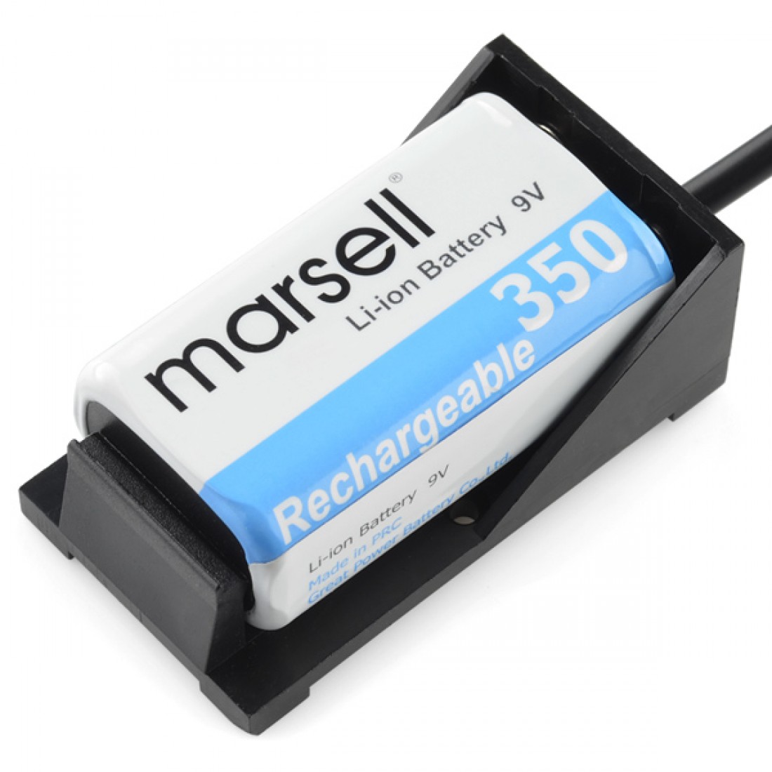
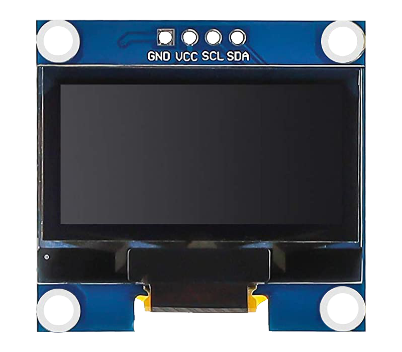
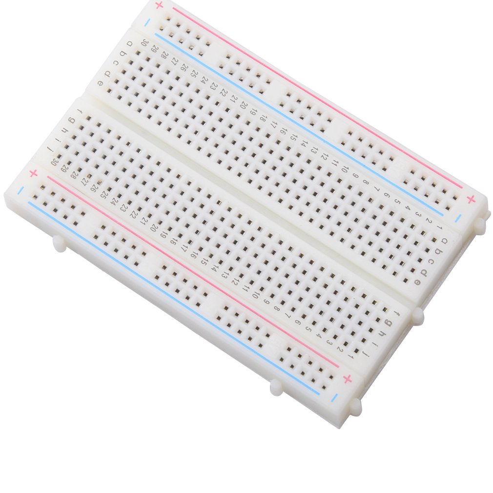
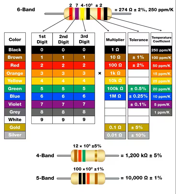
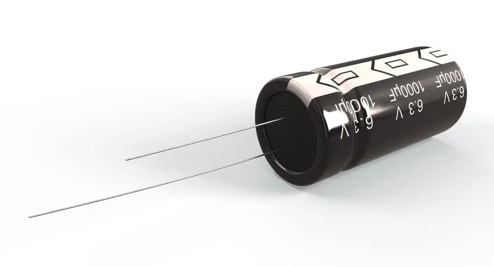
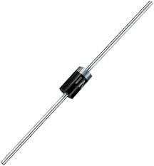
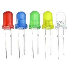
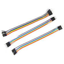
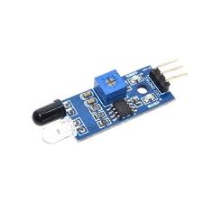
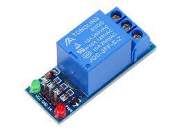
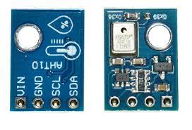
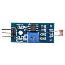
Gearbox Company provides its learners with kits that allow one to practice on thier embedded systems skills using the various components inside.
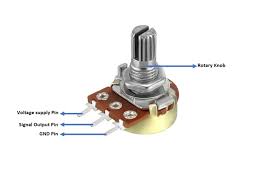
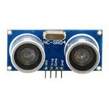
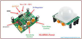
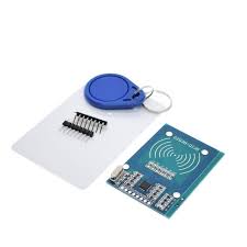
The components and their functions are as shown below :

Raspberry Pi Pico (RP2040) - This is a microcrocontroller that can be programmed both in C/C++ and python, is low-cost, high performance board with flexible digital interfaces.
Its features include :
  • RP2040 microcontroller chip designed by Raspberry Pi in the United Kingdom
  • Dual-core Arm Cortex M0+ processor, flexible clock running up to 133 MHz
  • 264kB of SRAM, and 2MB of on-board flash memory
  • USB 1.1 with device and host support
  • Low-power sleep and dormant modes
  • Drag-and-drop programming using mass storage over USB
  • 26 × multi-function GPIO pins
  • 2 × SPI, 2 × I2C, 2 × UART, 3 × 12-bit ADC, 16 × controllable PWM channels
  • Accurate clock and timer on-chip
  • Temperature sensor
  • Accelerated floating-point libraries on-chip
  • 8 × Programmable I/O (PIO) state machines for custom peripheral support
ESP32 Dev Kit Module - This board is mainly programmed in C/C++ in the arduino ide and has wifin and bluetooth capabilities.ESP32(Espressif Systems) is a series of low-cost, low-power systems on chip microcontrollers with integrated Wi-Fi and dual-mode Bluetooth.
ESP32 Camera Module - The ESP32-CAM is a very small camera module with the ESP32-S chip. Besides the OV2640 camera, and several GPIOs to connect peripherals, it also features a microSD card slot that can be useful to store images taken with the camera or to store files to serve to clients.
NOTE : The ESP32-CAM doesn’t come with a USB connector, so you need an FTDI programmer to upload code through the UOR and UOT pins (serial pins).
Its features include:
  • The smallest 802.11b/g/n Wi-Fi BT SoC module
  • Low power 32-bit CPU,can also serve the application processor
  • Up to 160MHz clock speed, summary computing power up to 600 DMIPS
  • Built-in 520 KB SRAM, external 4MPSRAM
  • Supports UART/SPI/I2C/PWM/ADC/DAC
  • Support OV2640 and OV7670 cameras, built-in flash lamp
  • Support image WiFI upload
  • Support TF card
  • Supports multiple sleep modes
  • Embedded Lwip and FreeRTOS
  • Supports STA/AP/STA+AP operation mode
  • Support Smart Config/AirKiss technology
  • Support for serial port local and remote firmware upgrades (FOTA)
9V Battery and Battery Holder - It allows you to securely attach a battery to your project and power it.
OLED Display(1.54in) - It offers 16 grayscale white with a 128 ×64 resolution and optional SPI or I2C interfacing
Breadboard Mini - This is a prototyping board that allows you to quickly make electrical circuits and test them.
Resistors(220, 1k, 5k, 10k) - These are used to regulate the current flowing in a circuit as well as adgust thevoltage levels in applications where a pull-up or pull-down resistor is needed.They are also color coded to siginify their resistance values.
Capacitors(0.22UF, 0.1UF, 0.15UF, 0.33UF) - This is a charge storing device is mostly used to smoothen sudden changes in volatage in a circuit by discharging when the supply voltage drops.
Push Buttons - It allows for momentary contact between 2 different pairs of pins.
IN4001 Schottky Diode - This is a semiconductor device that is is used to allow current flow in only one direction.The side which is marked by a strip indicates the side that is to be connected to the positive terminal.
LEDs(Red,Blue,Yellow) - Light Emmitting Diodes are small devices that produce light acoording to their color when connected to a voltage source usually 3.3 volts and below but varies depending on the led color with red requiring the least voltage.
Jumper Cables(M-M, M-F, F-F) - They are wires with conector pins on their ends that are used to quickly make electrical connections on the breadboard linking other devices without the need for soldering.
Potentiometer(10k) - This is a variable resistor that allow it to produce an analog volatage ranging from 0 to VCC.
HC-SR04 Ultrasonic Distance Sensor - This is a device that is used to measure distance of objects without contact.It's based on echos as it sends a signal and receives its echo then measures the time between sending and receiving which is used to calculate the distance.
HC-SR501 - This is a motion sensor that produces a signal once an object moves within its sensing radius. It is usually used together with devices such as lamps that light up when someone enters a room.
RFID Card Reader/ Detector Module Kit - Radio Frequency Identification comprises of a tag and a reader. The reader produces a radio frequency that is sent back from the tag and reprensents a character key that is unique for that particular tag. This is usually used in access control systems and even in storing changable information such as bank balances on credit cards that are updated when we make a puchase and pay with our cards.
Micro Servo 9g TS180 Degree - This is a small servo motor that can rotate 180 degrees, 90 degrees in each direction. It can easily be controlled by code using the appropriate servo library.
IR Infrared sensor module - It is a light sensor that has a transmitter and receiver tubes which send a frequency of Infrared light and reads the reflected signal and determines its value between the thresholds you give it e.g black and white.It is usually used in line following robots
IR Remote Control Module Kit - Latest infrared wireless remote control kit consists of Mini Slim 38KHz IR remote control and infrared receiver modules, Mini Slim infrared remote control with 17 function keys, firing distances of up to 8 meters, ideal for a variety of devices in the control room.This IR Remote Control Kit is ideal for implementing an IR remote control for many projects including controlling robotics since the remote includes direction keys and basic number keys without all the unnecessary key clutter found on remotes used for TV style control.
5V Relay 1 Channel Relay Module - It is a module that enables one to control a much larger voltage circuit by acting as a switch that can be opened or clodes from by signals from a microcontroller.
AHT10 Temperature and Humidity Sensor - Used to measure the temperature level and humidity percentage in the air by outputing a digital signal in standard I2C format.
Photoresistor Light Detection Sensor - It is a device that measures the intensity of incident light by changing its resistance with it being highest when light has low intensity and minimum resitance when light has maximum intensity.
FT232 FTDI Breakout Board - It is a board used to convert usb signals to serial signals

Overview of RP2040 and RPi Pico, including GPIOs

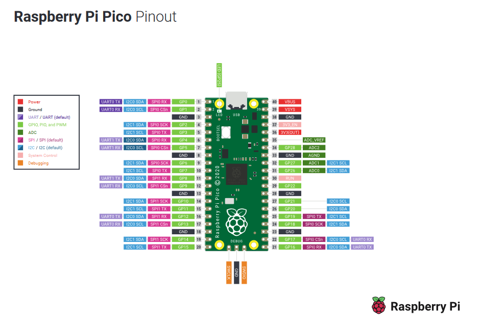
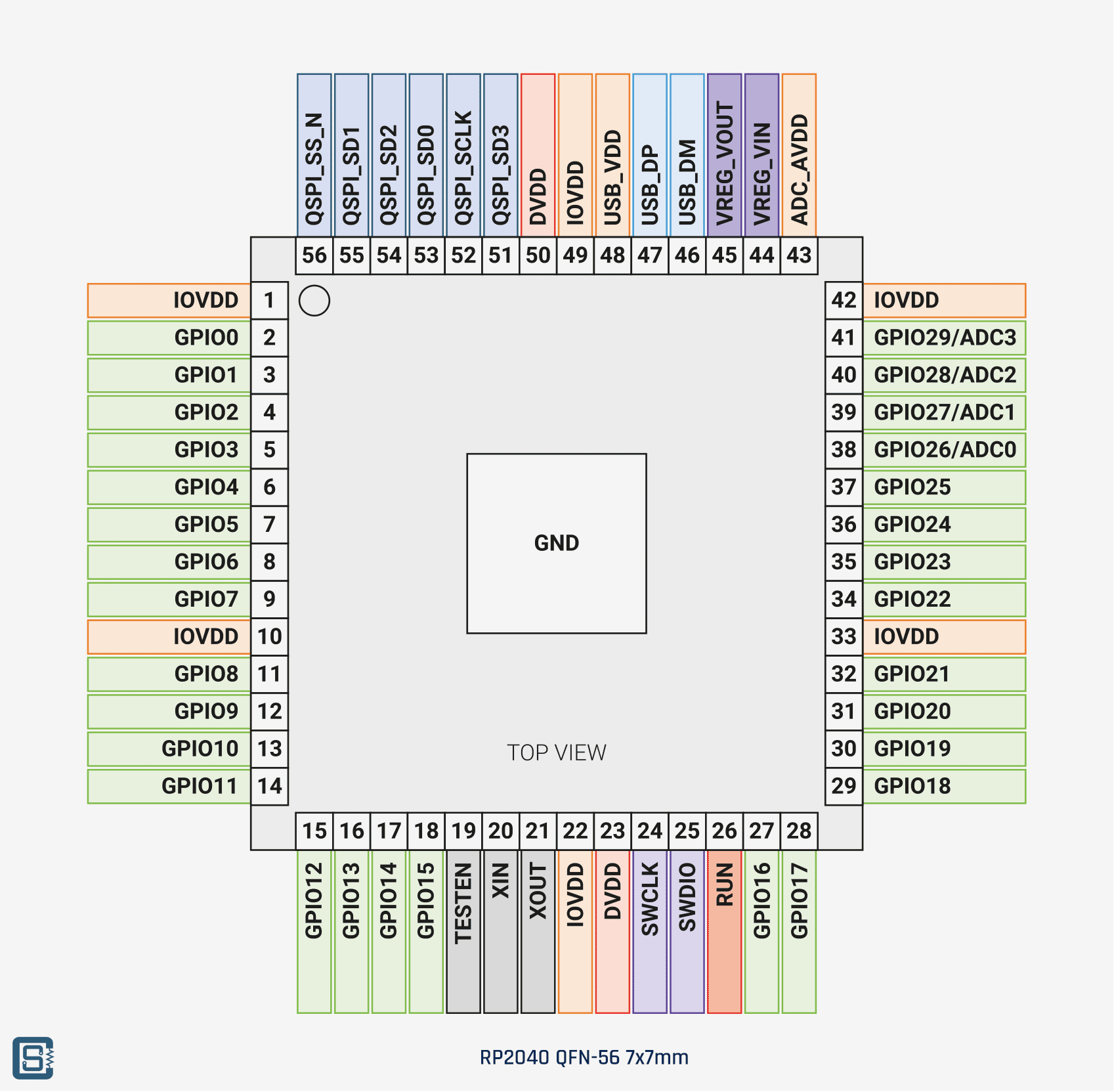
RP2040 - RP2040 is the debut microcontroller from Raspberry Pi. It brings our signature values of high performance, low cost, and ease of use to the microcontroller space.

RPi Pico - An RP2040-based microcontroller board

Introduction to IDEs - Thonny, Arduino, Pico C/C++ SDK

An integrated development environment (IDE) is a software application that helps programmers develop software code efficiently. It increases developer productivity by combining capabilities such as software editing, building, testing, and packaging in an easy-to-use application.
A software development kit (SDK) is a set of platform-specific building tools for developers. You require components like debuggers, compilers, and libraries to create code that runs on a specific platform, operating system, or programming language. SDKs put everything you need to develop and run software in one place. Additionally, they contain resources like documentation, tutorials, and guides as well as APIs and frameworks for faster application development.e.g. Java Development Kit
Thonny - It is a python IDE that will be used to program the Raspberry Pi Pico using Micropython.
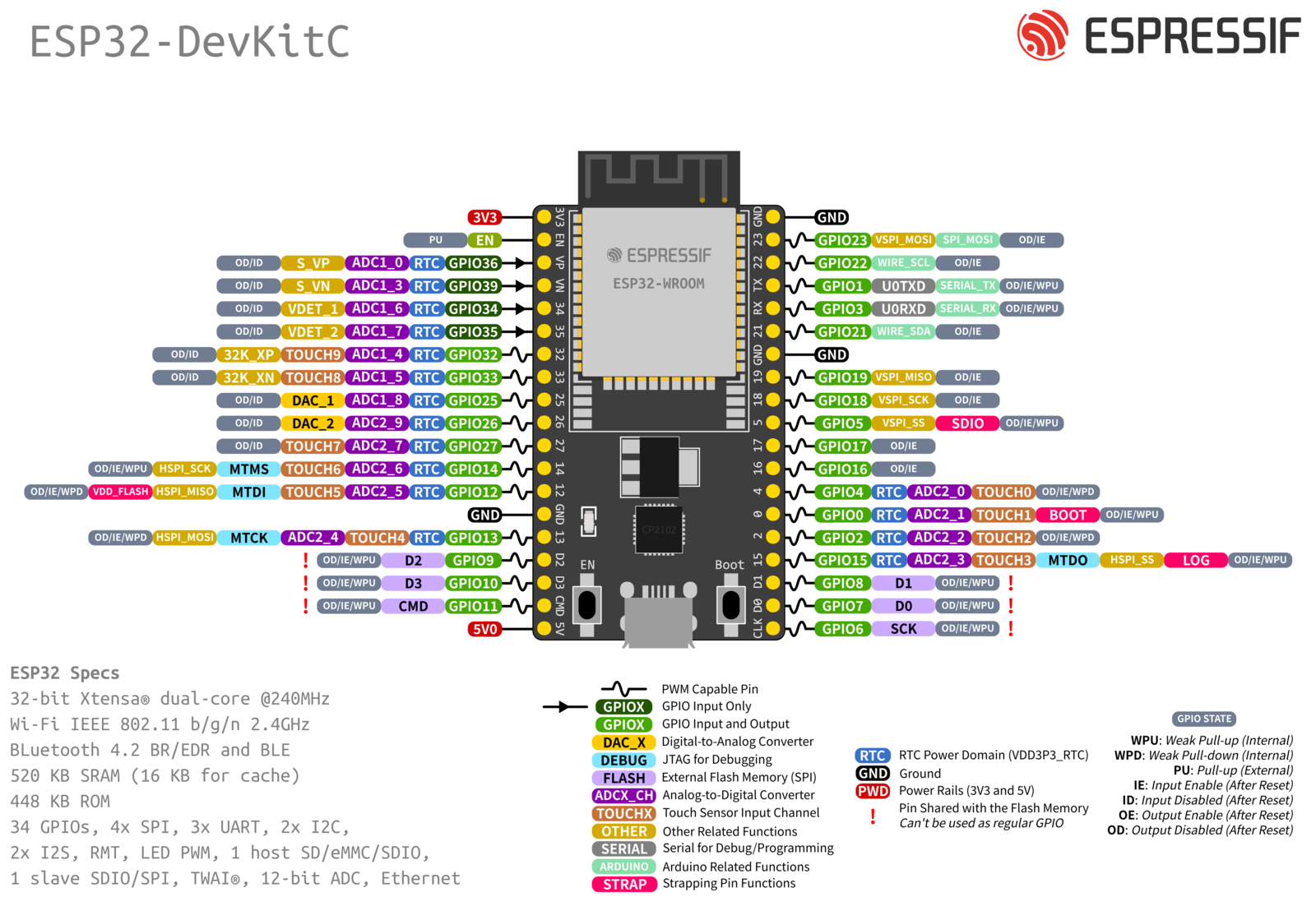
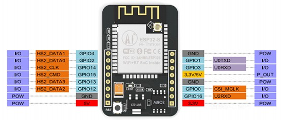
Arduino IDE - It is a C/C++ IDE that will be used to program a very wide variety of boards that support this language such as arduino and ESP32.

Installation of Thonny IDE and Micropython

Steps to install Thonny IDE:

  1. Go to Thonny IDE Download
  2. Download the version for Windows and wait a few seconds while it downloads.
  3. Run the .exe file.
  4. Follow the installation wizard to complete the installation process. You just need to click “Next”.
  5. After completing the installation, open Thonny IDE. A window as showing the Thonny workpace should open.

Steps to install Micropython Firmware:
  1. Go to the MicroPython Downloads page: Micropython Download.
  2. Select the type of board you're using.
  3. Download the latest release.

Blink Pico LED using MicroPython

Here's Micropython code that causes an led to blink:

                            
                    from machine import sleep    
                    from time import sleep
        
                    led=Pin(26,Pin.OUT)
    
                    while True:
                        led.value(1)
                        sleep(1)
                        led.value(0)
                        sleep(1)
                        
                        
Here's a link of the same in wokwi: Blink led simulation in Micropython

Blink LED using Pico, C/C++ SDK

Here's the code in C used to blink an led:

                                
        int led=26;

        void setup() {
            // put your setup code here, to run once:
            pinMode(led,OUTPUT);
        }
        void loop() {
            // put your main code here, to run repeatedly:
            digitalWrite(led,HIGH);
            delay(1000);
            digitalWrite(led,LOW);
            delay(1000);
        }
                        
                    
Here's a link of the same in wokwi: Blink led simulation in C